By Keith H.
Playing Spacewars.
My last article explained that the DEC 340 Monitor pointed at and shot dots from an electron gun to light up spots on its screen. That was my magic chant, the method of how the DEC 340 drew its pictures as a collection of dots.
Every picture a DEC 340 ever showed was made of dots flashed onto its radar tube by the tube electron gun. Reproducing the technology that poked those dots onto the tube is what I do now. It is a fascinating puzzle to solve, even inspiring,
Now is the winter of my discontent
Made glorious summer by this DEC of 340;
And all distracting clouds that lowered upon my dome
Into the deep sea must be buried.
Or else I won’t get it done. I don’t have full documentation and parts are missing. It is a puzzle I don’t have all the pieces for; the challenge of coming up with missing puzzle pieces and getting them to work and fit together, inspires me, but that’s not enough. It must consume me with passion! A hero’s journey has begun and heroes can’t be distracted. There is no time for it. The devil is in the details and there are a lot of details in this project. Trying to keep track of all of them is challenging so I make it fun. This blog series will catch up to the actual work of that challenge later but for now I need to describe the scenery a bit more. I hope a transistor will appear in my next installment but I have to set the background for them or they aren’t very interesting characters. They can be captivating entertainers but you have to get them in the right venue or they won’t amuse. More background is needed.
Designing the original DEC 340 may have been an easier job then mine. Don’t think that is a complaint, it is only an observation. The DEC 340 circuits were already in use in a preceding DEC monitor, a monitor that DEC designers had full documentation for. This was a monitor they could touch and turn on. The designers had drawings and net-lists which described how all the plug in System Design Modules were interconnected to create the monitor. The most useful document I have, is this one.
http://www.bitsavers.org/pdf/dec/graphics/H-340_Type_340_Precision_Incremental_CRT_System_Nov64.pdf
Many thanks to a reader who upon reading the first article of my series supplied this link. The copy I had must have been a copy of a copy of a copy and was relatively illegible. This one is crisp and clean. Many thanks.
The document is a maintenance manual intended for limited distribution. It has a lot of good information but it is not an engineering file that would have everything I need to know to reconstruct a DEC 340. It contains documents which give a good understanding of how the DEC 340 works. It is detailed enough to perform maintenance on the machine. It’s my Rosetta Stone. I’m using it to translate old to new, after enough pondering and understanding.

DEC engineers had all the bright and shiny System Design Modules that they needed, building blocks from which the DEC 340 is made. The DEC 340 was an evolutionary design which evolved from the DEC 30E, an earlier DEC monitor. The original 340 design did not start from scratch. The designers had a working monitor and a clear goal. I have a DEC 30E manual similar to the DEC 340 manual. It has information that describes some of the missing chips off my stone.
The goal seems to have been to improve DEC 30E performance. Other considerations may have motivated a new design, but circuitry differences tell me that performance enhancement was the big goal.
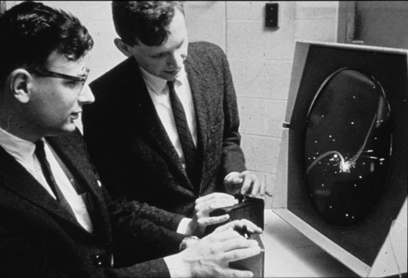
The 340 was built on top of the 30E design. The DEC 340 has additional circuitry the 30E did not have but all the tube driving circuits the DEC 30E had were found inside a DEC 340. A 30E is shown at the top of this article playing Spacewars. The DEC 30E used the same tube as the DEC 340 and a 30E manual was good to find. It documents the tube neck circuitry better than the 340 manual does.
It may be that designing the 340 was an easier job because the 30E monitor already existed but I’ll guess the original 340 designers were also told something like, ‘you’ll have it done by next Tuesday right’? That not actually being a question. A complication of course, which at the end of the day would make their job a lot harder than mine. Especially if tomorrow were already Tuesday.
The 30E used the DEC point and shoot method of drawing dots on its screen like the DEC 340 and later DEC monitors did, but the 30E could not show as many dots on a screen as a 340. The DEC 340 uses tricks to get more dots on its screen. Displaying Spacewars makes for a great photo, but I don’t see a star field of dots as much of a performance test. I’d like to see how it did at rendering a few sentences. I suspect a few sentences would push 30E hardware to it’s limit. Magnetic deflection of Cathode Ray Tube beams is band limited. Band limited means the yoke magnetic field can’t be changed as fast we need it to be, to steer a pointed-at spot around as fast as we want. Spending a few moments considering how many dots are in a picture made up of all dots, and how much time is allowed to draw them all to prevent screen flicker, shows how fast an ideal DEC 340 tube yoke needs to be.
In a DEC 340, a square in the center of the CRT is used for display. It is a little less than 10 inches on a side, and each point in the square has a unique ten bit X and Y address. Ten bit addressing allows for 1024 X and 1024 Y values. Spots outside this center screen square can’t be pointed at.
If only one fiftieth of a second is allowed before a screen must be redrawn or it flickers, an all white screen needs to point and shoot at more than fifty million dots in a second, because there are over a million dots in an all white screen. This allows for less than twenty nanoseconds of time to draw a dot. Point and shoot magnetic deflection can’t keep up so an all white screen on a DEC 340, that does not flicker, is impossible. But a whiter screen than that which can be drawn on a DEC 30E is possible with a DEC 340. Improvements were made.
In the computer room at the Living Computer Museum, in Seattle Washington, there is a CDC 6500 with a working DD 60 display attached. The tubes in that display use electrostatic deflection, which does not have the inherent bandwidth problem that magnetic deflection has. The DD 60 displays are also large pieces of furniture. A tube which uses electrostatic deflection has to be about three times longer than it is wide or the electron beam will only make a small square in the center of its screen. An electron beam has only a very brief time in which to be deflected as it passes between two electrically charged deflection plates, the resulting deflection angle is limited.
A vintage monitor made by Hewlett Packard, the HP 1300, got around the geometry problem by a special (and patented) innovation, a special grid inside its CRT which enlarges a picture on the screen. The Living Computer Museum has a DEC PDP computer with a working HP1300 attached. It is a custom implementation used at the University of Oregon as a research device for many years. The HP1300 was a monitor, but it was not a computer monitor. The HP1300 requires external X and Y voltages with a gate signal to move the beam around and to turn it on and off. The CRTs in HP1300s look like old TV tubes, wider than they are tall, but internally they are more like oscilloscope tubes with electrostatic deflection plates. To me, they have a one of a kind special delight because of the innovation.
Electrostatic deflection, for whatever reason, was not an option for DEC, so the best that could be done with magnetic deflection was attempted. The goal was to make something useful. Thinking of a computer monitor as a device to represent photo images, and not as something that only outputs useful data at the time, was a figment of somebody’s imagination. Probably more than one somebody had the same figment, but practically it was for the time, a wild dream. Digital images could not be read from a sea of cheap memory as they are today. At the time the DEC 340 was made, everything in an image was programmed. There were no digital cameras. Computer monitors were a different animal and people thought of them totally differently than they do today. Drawing a line took time, Drawing two lines took more time. Not everything in a picture had the same ‘cost’ but all modern computer monitor pictures do have the same ‘cost’, a cost that modern hardware has no problem keeping up with. The time it takes to read a image from memory. Things were different in the days of tube monitors like the DEC 340.
A DEC 30E takes thirty five microseconds to set X and Y magnetic fields to point to a spot on the screen. With 1048576 points in a square, that is more than 1000 times slower than we need to light up every point in a display screen square sans any flicker. I guessed at fifty refreshes a second, but that is a reasonable guess. Improvement in response time is obviously desirable, and a 1000 to 1 ratio is a lot of room for improvement. Is the picture as bleak as it could be? The answer to that question, it turns out, is no.
A DEC computer at the time, would need several microseconds to set X and Y values of a point. Several microseconds is not a lot different than the 35 microseconds it takes for a 30E magnetic field to settle on a pointed-at value. Certainly a lot less than a 1000 to 1 ratio. Not much 30E speed improvement is needed before a DEC computer that a DEC 30E attached to limits performance not the 30E monitor. This is similar to the weakest link in a chain being the link that defines how strong a chain is. Magnetic deflection would not be the limiting factor once the 30E could be made to outperform a DEC PDP computer. The DEC 340 attempted to implement that improvement. Two different things were done to get more spots on the screen.
The response time to settle the magnetic field between adjacent points was reduced by blending an open loop response with a closed loop response. That’s engineering talk most of you won’t have a clue about understanding and I’ll let that be my concentration the next time I write an article installment. The 30E was an entirely closed loop device. I’ll let that be my first sentence for the next installment. I’ll go from there.
The second thing that was done was to make the interface between the DEC 340 and a host computer more elaborate so entire lines could be easily described. A program that draws lines and dots is going to obviously be shorter than one that draws just dots. The DEC 340 takes line segments and calculates point positions on these lines by itself, to draw the lines as points. The DEC 340 is a programmable device able to take some of the burden of ‘vector’ programming away from the host computer it’s attached to. The DEC 340 could be set in different modes to ease information transfer between its host computer and free up CPU clock cycles. Description of these modes will wait for a future day because that has to do with device logic, for now I’m concentrating on the electronics that drive the CRT.
Once DEC marketing saw something describing improved performance, I’ll guess pressure to ‘ship it‘ inside the DEC eco-sphere must have been intense. Getting into the details of the electronic circuits that produce that magnetic deflection speedup, I’ll do in my next installment.