By Keith H.
Previously I introduced my DEC 340 monitor restoration project. I promised then to describe how the DEC 340 monitor worked.
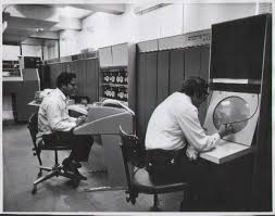
I will, but that explanation won’t mean much without some context first. After the context the special magic that makes the DEC 340 different from other computer monitors will be revealed.
High definition images are ubiquitous now and a comfortable magic hides the mystery and complexity of what it takes to show a picture on a computer screen to us. High definition images are everywhere and they use a refined magic that took a century to evolve. The story began in 1869 with the Crookes tube.
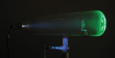
Crookes Tube (High Definition Computer Image)
The DEC 340 monitor story is part of the story of this magic. The technology used in the DEC 340, a few steps back from what we now have, had limitations unknown today. My personal fascination with the DEC 340 is about what was done to overcome these limitations.
Today’s flat panels depend on high speed digital electronic circuits which did not exist when the DEC 340 was built. These circuits would later become the technical background of modern computing as we know it and without them computers as we know them could not exist.
Cheap memory, being able to hold a supercomputer in the palm of your hand, the ability to process images in real time, and the ability to make flat panel monitors with high definition images all resulted from the revolutionary technical innovation of packages of small high speed digital electronic circuits.
Today’s world has the technology to give us realistic images but in the world the the DEC 340 comes from nothing much better could be done. The DEC 340 used discrete components, the only available. A cell phone today made from similar discrete components would be as big as a car and would cost more. It also would not work.
Size and the speed of light would prevent its circuits from operating fast enough to do the jobs they need to do. In electronics where speed is important, size matters and smaller is better for high speed.
Two components in the DEC 340 are huge. The radar tube and a magnetic yoke around the radar tube neck that steers an electron beam around to paint a picture can’t be made smaller. The size of the magnetic yoke limits the complexity of an image which can be drawn. Yokes have a property called inductance which I will describe, and inductance goes up with size. Inductance slows things down. This will be important later.
I look at the DEC 340 circuits. They are fascinating just the way they look but the more I study them the more interesting they get. Component colors on the parts don’t get brighter, the metal shinier, or anything like that, but my appreciation for these circuits grows with time. The circuits are not sloppy. Lots of effort went into their design and they pushed the limits of what could be done with bipolar transistor technology, then, and even now. These circuits had to do as much as they could in a very short period of time. They were designed to push the limit of what can be done.
Between today’s flat panels and the DEC 340, computer monitors of a different kind existed. These monitors were raster scan devices. They used Cathode Ray Tubes CRTs like the DEC 340 did but these tubes were like old TV tubes and worked the same basic way. Internal storage of pictures in computer memory files even today reflects a raster-like form. Information off picture files once had to be read sequentially to form lines for these raster scan monitors. The information was stored in a way that directly supported raster-scan formats. Raster scan monitors are a link between monitors like the DEC 340 and the computer monitors we have today.
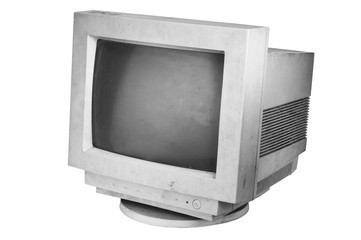 Raster Scanner
Raster scan monitors would be the backbone of computer displays for many years and television did exist when the DEC 340 was built. But to use a television display with a computer needs cheap memory which had not yet been invented. Raster scanning was not a viable option for computers in the early 1960’s. Memory cost too much.
A bit is needed for every spot on the screen in a raster scan device. The DEC 340 screen would need to store 1024 bits for each horizontal line and there would be 1024 lines to read out in every scan. That would be 1048576 bits total. A trivial amount of memory today, but that is more memory than a PDP 7 even shipped with. PDP 7s only had 73728 bits or 4 K words on delivery. It could be expanded but only to 64 K words.
TV of the era was an all analog process and involved no digital storage at all. A TV camera recorded an image by tracing a raster on a camera screen and a receiver reproduced this camera generated raster on its screen in real time by duplicating the intensity variations produced at the camera.
Video tape storage was possible but this only recorded an analog copy of an image and practically was only the same as a real time analog signal but delayed. A TV receiver could not tell the difference between the two. Digital manipulation of a raster image could not be done until enough memory was available to store an entire screen of image data so it could be later read out. It would take a few years before technology could catch up and provide enough cheap memory to store data for an analog video signal.
Cathode Ray Tube monitors be they raster scan devices or devices like the DEC 340 have an electron gun that shoots a very thin beam of electrons down the center of the tube so that a spot in the center of the screen glows if the beam is on. Without a magnetic deflection yoke this spot would stay in the center of the screen and could not move. That is not very interesting, but for me it will be a very satisfying thing to see when I get that far.
A magnetic yoke is needed to deflect the electron beam to other places on the CRT screen. This magnetic deflection yoke moves the spot lit up on the screen around by current variations that change the magnetic field around the tube.
Current changes can’t be made infinitely fast because the yoke has the property of inductance which I mentioned earlier and inductance tries to keep yoke currents from changing. Inductance is like momentum which tries to keep you going forward when you try and stop running. Inductance wants to keep current flowing like momentum wants to keep motion going.
A CRT picture is made by moving the spot on the screen that is lit up around so fast its motion is invisible. The entire traced path looks lit up all at once. Turning the electron beam on and off while the spot scans turns the illuminated spot on and off. These methods mixed together allow an image to be drawn on a CRT screen.
Inductance in the magnetic yoke limits how fast yoke current can change and the whole picture has to be redrawn as soon as the whole picture is finished being drawn or it blinks out. The limit on how fast the spot can move limits the complexity of any picture that can be shown. A raster scan covers the entire screen and breaks it up into horizontal lines. Inductance limits the number of lines that can be drawn but a useful number in a raster is achievable.
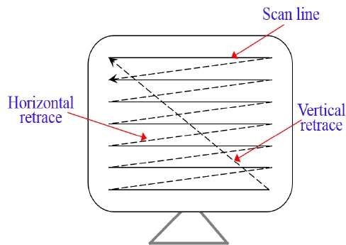
A Raster Scan
All the electronics has to do in a raster scan monitor is reproduce the raster and turn the beam on where the picture to be shown overlays the raster. Picking a raster that electronic circuits can support easily can be a judicious choice making electronic design of a raster scan monitor a well defined problem. The raster is a repetitive pattern the yoke currents simply retrace over and over. This is different and simpler than what the DEC 340 does. The pattern traced depends on the picture in a DEC 340. The more complicated the picture the more complicated a pattern that draws it must be.
Only a short period of time is available to draw a picture. A spot lit up by the CRT electron beam will go dark quickly once the electron beam is removed. For a picture to remain visible it must be continually redrawn. With only a short time to draw a picture before it has to be redrawn or the screen flickers, and with the complexity of a traced pattern dependent on picture content, DEC 340 electronics had to be made as fast as possible. Unlike a raster scan where good enough electronics is just fine.
Unlike a raster device, positioning the electron beam is done by computer code running a computer program with instructions to control the DEC 340 in an attached computer. The decision to refresh the screen is also made by program code. The alternative to a raster scan is called a random or vector scan because a vector monitor can draw an arbitrary line or ‘vector’ of any length in any direction starting from any point on the screen. Enough such lines when displayed together make a picture. When memory is an issue a vector representation of a picture will generally save space. Location direction and length will define a line. In the picture below only information for five lines is needed. The arrows are only showing movement and are not displayed. Saving this picture in vector form will save a lot of memory over a raster equivalent.
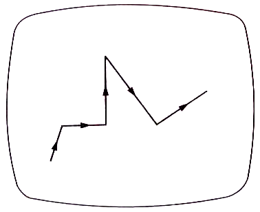
A Vector Scan
The DEC 340 interestingly is neither a vector device nor a raster scan device though it is very much like a vector monitor. The DEC 340 points to a spot on the screen. The electron gun is fired for half a microsecond or half a millionth of a second after the magnetic yoke field stops changing when a point on the screen is pointed at. The magnet field currents are then set to point to a new place and another dot on the screen is lit up for half a microsecond.
Enough such dots displayed together make a picture. Different modes can be set in the DEC 340 to make writing to the screen easier. Two different ‘vector’ modes allow a vector to be specified which is then rendered automatically by the 340 as a series of inter- connected dots to make a line. The distinction is that in the DEC 340 only dots are created to make a picture. Yoke currents never change when a spot is being lit up.
A DEC 340 ‘dot’ program with more complexity than an equivalent raster picture is not hard to imagine since a raster scan never crosses itself in a scan. Circuits in the DEC 340 however get pushed to their limit because the path between dots can easily cross over and over again. The dots can be selected in any order so different paths of different complexity could render the same picture.
This time I’ve presented a basic description of how the DEC 340 works. It is quite a bit different than computer monitors which came later but its design was the best that could be done at that time for any reasonable cost. It was a good design for the technology of the day. Next time I’ll be getting into some details of the design enhancements made to increase the speed at which DEC 340 ‘dots’ can be drawn. Remembering that the more dots we can draw in a given time the more complex a 340 display image can be. I’ll be comparing the DEC 340 monitor with an earlier DEC monitor, the DEC 30E.