By Bruce S.
I have 4500 modules in the CDC 6500, and it isn’t always easy to debug them in the machine, because convincing the machine to wiggle its lines so I can check each transistor on a particular module is difficult.
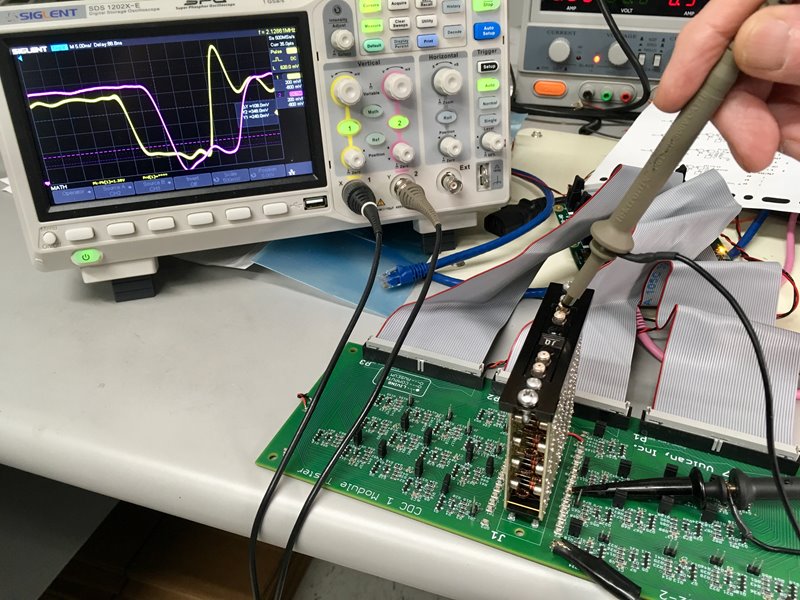
In order to make this problem a little easier, I have built a cordwood module tester:

It has taken a couple of revisions to get the pin drivers correct, but it does useful things for me when I need it to. The three cables going out the back go to a Mesa Electronics 7i80 FPGA board, which I use for driving signals to the module under test. I have written some hardware for the FPGA, in VHDL, that knows how to talk to the tester board.
I have also written an assembler in Perl, to assemble stimulus commands I write, to the appropriate VHDL that gets included into the FPGA. Here is a sample of what I feed into the assembler:
# P14 = T70 negative pulse
# P17 = clock gate
# set the pins:
p1=h p2=h p3=h p4=h p5=h p6=h p7=h p8=h p9=h p10=h p11=h p12=h p13=h p14=h p15=h p16=h p17=h
p18=h p19=h p20=h p21=h p22=h p23=h p24=h p25=h p26=h p27=h p28=h
# scope sync pulse on unused pin
p1=h
p1=L
# run clocks for a bit...
P17=h
P14=L
P14=h
P14=h
P14=h P17=L
P14=L
Each line represents what it should do for the next 20 nano-seconds. This results in a table that gets glued together with some header and trailer bits to create the VHDL input file. Here is the output listing:
 # P14 = T70 negative pulse
 # P17 = clock gate
 # set the pins:
 0 0ns 0xffe0000 p1=0 p2=0 p3=0 p4=0 p5=0 p6=0 p7=0 p8=0 p9=0 p10=0 p11=0 p12=0 p13=0 p14=0 p15=0 p16=0 p17=0
 1 20ns 0x0000000 p18=0 p19=0 p20=0 p21=0 p22=0 p23=0 p24=0 p25=0 p26=0 p27=0 p28=0
 # scope sync pulse on unused pin
 2 40ns 0x0000000 p1=0
 3 60ns 0x0000001 p1=1
 # run clocks for a bit...
 4 80ns 0x0000001 P17=0
 5 100ns 0x0002001 P14=1
 6 120ns 0x0000001 P14=0
 7 140ns 0x0000001 P14=0
 8 160ns 0x0010001 P14=0 P17=1
 9 180ns 0x0012001 P14=1
 10 200ns 0x0010001 P14=0
 11 220ns 0x0010001 P14=0
The listing shows the memory location, what time that instruction should execute, the actual bits in hexadecimal notation, and what the source file said.
This handy little tool has enabled me to fix 4 out of 5 of the UA modules I had replaced in the CDC, and to know what was wrong with the other one.