« Back to Blog   

Connecting to the PDP-7
August 17, 2019
By Jeff K.

My project was to solder 50-pin ribbon cables to the 55-pin connectors. This will allow us to easily connect to external logic.

55-pin round connector
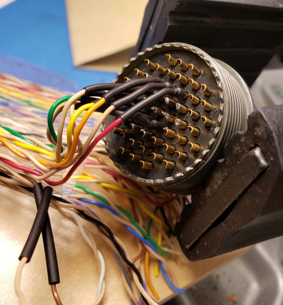
Pin numbers spiral in, so it is best to begin soldering at the inside and work out. Here are the first four pairs of wire. The green wire is the 25th pair of the ribbon cable.

Each wire has heat-shrink tubing to both insulate and to provide structural strength.

55-pin round connector
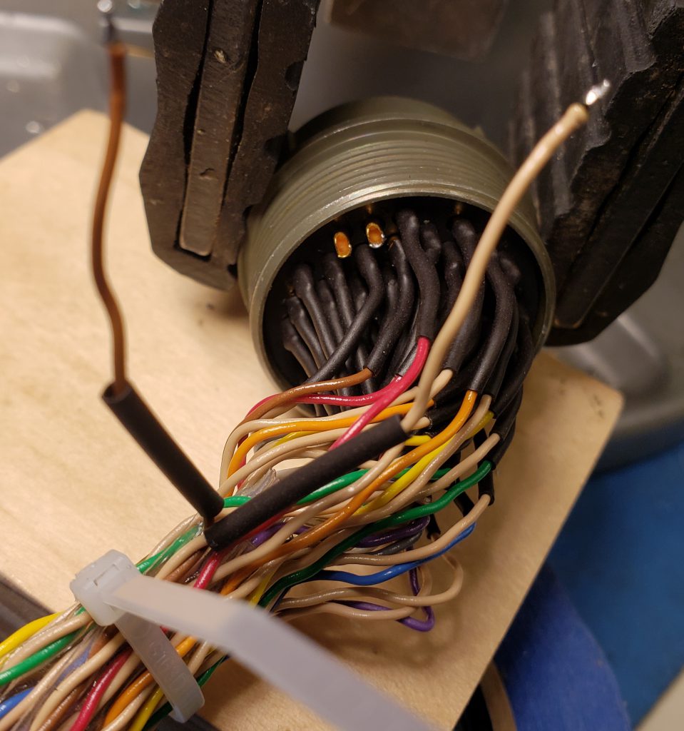
This is the other connector, and being of the other gender it spirals the other direction. The final two wires are ready to be soldered.
About the Author
Jeff K.
Vintage Hardware Restoration Engineer
As a kid, Jeff became interested in how machines work after reading Benny the Bulldozer by Edith Thatcher Hurd (1947). In high school, Jeff took his first computing classes, including a math class that taught him to plot a spirograph on a HP 91000B calculator. Jeff eventually enjoyed a thirty-five year career as a technician with Strobe Data, before joining LCM+L’s engineering team to work on the Xerox Sigma 9 mainframe computer. Today you can find Jeff tinkering away upstairs on the IBM 360/30.

He continues to plot spirographs on computers.

Category Tags
Hardware
Restoration